Electrical Engineering

Effect of Temperature On Resistance | Resistance Temperature Coefficient

Effect of Temperature On Resistance | Resistance Temperature Coefficient

Fundamental of Electrical Engineering | Effect of Temperature On Resistance| Resistance Temperature Coefficient

Effect of Temperature On Resistance:-

The electrical resistance changes with the change of temperature. The resistance does not only increase with the rise in temperature but it also decreases in some cases. In fact, for the different type of materials, the amount of change in resistance due to change in temperature is different which are discussed as follow.

Metal: The resistance of all pure metals increases linearly with increase in temperature over a limited temperature range. At low temperature, the ions are almost stationary. As the temperature increases, the ions inside the metal acquire energy and start oscillating about their mean positions. These vibrating ions collide with the electrons Hence resistance increases with increase in temperatures.

The resistance of all metals such as tungsten, copper, aluminum etc. increases linearly with increase in the temperature over a limited temperature range. For e.g. the resistance of copper is 100Ω at 0°c then it increases linearly upto 100°c. At a temperature of -234.5°c the resistance of copper is almost zero as shown in the figure.

Effect of Temperature on Copper Metal

Hence Pure metal have positive temperature Coefficient of Resistance.

Alloy: The resistance of almost all alloys increases with increase in temperature but the rate of change of resistance is less than that of metals. In fact, the resistance of certain alloys such as Manning, Eureka, and Constant show practically no change in resistance of a considerable range of temperature. Due to this property, the alloy is used to manufacture the resistance box.

Semiconductor, Insulator, and Electrolyte: The resistance of semiconductor, Insulator, and Electrolyte(silicon, Glass, Varnish etc) decrease with increase in temperature.At zero temperature, the semiconductor behaves as a perfect insulator.  As the temperature increases, some of the electrons acquire energy and become free for conduction. Hence, conductivity increase and resistance decrease with increase in temperature.

Semiconductor has negative temperature coefficient of resistivity therefore since with the increase in the temperature the resistance decreases.


Resistance Temperature Coefficient:

The change in resistance of a material with the increase in temperature can be expressed b means of the temperature coefficient of resistance.Consider a conductor having resistance Ro at 0°c and Rat t°c. From the above discussion, we can conclude that the change in the resistance i.e (Rt – Ro) is

  1. Directly proportional to the initial resistance Ro
  2. Directly proportional to the rise in temperature t°c.
  3. Depends on the nature of the material for conductor metals and alloy

Hence

(Rt – Ro) ∝ Rot

(Rt – Ro) = αRot

Rt  = Ro(1 + αot)

Where αo is constant and called as the temperature coefficient of resistance at 0°c and its value depends upon the nature of material and temperature.

Temperature-coefficient-resistancei

Effect of Temperature On Temperature Coefficient of Resistance

Let Rt1 and Rt2 be the resistance of the conductor at t1°c and t2°c respectively, and α1 and α2 be the corresponding temperature coefficient. Let the conductor is heated from initial temperature t1°c to the final temperature t2°c.

Rt2  = Rt1[1 + αt1 (t– t1)]——————– 1

Now the same conductor is cooled from t2°c to t1°c.

Rt1  = Rt2[1 + αt2 (t– t2)]———————2

Substituting equation 2 in equation 1

Rt2  =  Rt2[1 + αt2 (t– t2)] [1 + αt1 (t– t1)]

Or

1 = [1 + αt2 (t– t2)] [1 + αt1 (t– t1)]

=  [1 – αt2 (t– t1)] [1 + αt1 (t– t1)]

1

Note: If the temperature changes from 0°C to t°C then

2

Effect Of Temperature On Resistivity

The specific resistance or resistivity of a material depends on temperature. The change in temperature affects the resistivity of a material in the same way as it affects the resistance.The resistivity of metals increases linearly with the increase in temperature. Let ρt1 and ρt2 be the resistivity at temperature t1°c and t1°c respectively. Let m be the slope of the linear part of the curve.

3

The ratio m/ρtis called the temperature coefficient of resistivity at t1°c and is almost equal to α1.

ρt2  = ρt1 [1 + αt1 (t– t1)]

Note: If the temperature changes from 0°C to t°C then

ρt  = ρo [1 + αot]


Ques1. A piece of copper wire has a resistance of 50 Ω at 10°C. Whal is the maximum operating temperature if the resistance of the wire is to be increased by 20%? Assume α at 10°C = 0.0041°C-1.

Sol:- R1 = 50 Ω

R2 = 50 + 0.2 x 50 = 60Ω

t2 = Unkown temperature at which R2 will be 60Ω

Since

Rt2  = Rt1[1 + αt1 (t– t1)]

∴ R2  = R1[1 + α(t– t1)]

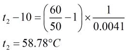
60 = 50[1 + 0.0041(t2 – 10)]

num

Ques 2. A certain winding made up of copper has a resistance of 100Ω at room temperature. if resistance temperature coefficient of copper at 0 °C is 0.00428 /°C, calculate the winding resistance temperature E increased to 50°C. Assume room temperature at 25°C.

R1 = 100 Ω

t1 = 25°C

t2 = 50°C

α= 0.00428 /°C

Now

num2

= 0.003866/°C

R2  = R1[1 + α(t– t1)]

R2  = 100[1 + 0.003866(50 – 25)]

=109.6657Ω

What is Turbine?

 What is Turbine? 

turbine is a device that harnesses the kinetic energy of some fluid - such as watersteamair, or combustion gases - and turns this into the rotational motion of the device itself. These devices are generally used in electrical generationengines, and propulsion systems and are classified as a type of engine. They are classified as such because engines are simply technologies that take an input and generate an output. A simple turbine is composed of a series of blades - currently steel is one of the most common materials used - and allows the fluid to enter the turbine, pushing the blades. These blades then spin and eject the fluid which now has less energy it did than when it entered the turbine. Some of the energy is captured by the turbine and used.

Turbines are used in many different areas, and each type of turbine has a slightly different construction to perform its job properly. Turbines are used in wind powerhydropower, in heat engines, and for propulsion. Turbines are extremely important because of the fact that nearly all electricity is generated by them.


Fig. No.-1


Fig. No.-2


What is an Electrical Isolator : Working & Its Applications

 What is an Electrical Isolator : Working & Its Applications:-

The isolator is one type of switching device, and the main function of this is to make sure that a circuit is totally not triggered in order to perform the preservation. These are also recognizable like isolation switches to isolate the circuits. These switches are applicable in industrial, distribution of electrical power, etc. High voltage type isolation switches are utilized in substations for permitting isolation of equipment like transformers, circuit breakers. Usually, the disconnector switch is not proposed for circuit control but it is for isolation. Isolators are activated either automatically or manually. This article discusses an overview of what is an electrical isolator, its types, and its applications.

What is Electrical Isolator?

The isolator can be defined as; it is one type of mechanical switch used to isolate a fraction of the electrical circuit when it is required. Isolator switches are used for opening an electrical circuit in the no-load condition. It is not proposed to be opened while current flows through the line. Generally, these are employed on circuit breaker both the ends thus the circuit breaker repair can be done easily without any risk.


Electrical Isolator is used to separate any type of electrical component from the system while the system is offline/ online. Isolator doesn’t include any kind of system for avoiding arching throughout disconnection. As in an electrical substation, an electrical isolator switch is mainly used for disconnecting a power transformer once it is in a no-load situation otherwise a little load is there. In full load condition, isolators don’t operate.

Working Principle

An electric isolator working principle is extremely easy as it operates in different ways like manually operated, semi-automatic, and fully-automatic. Sometimes, these are used like switches so-known as electrical isolator switches. This switch can be opened or closed depending on the necessity. However, several times, these are arranged in a fixed position permanently to maintain isolation like transformers, in electrical transmission lines, grid stations.

An electrical isolator switch is one kind of device used to isolate a specific circuit by maintaining as well as preventing flowing currents. These switches are used in electrical appliances like kitchen tools, power grids, etc. Isolator switches are available in different types like a single-pole, double-pole, 3-pole, 4-pole, fused, and battery isolator switches.

Operation of Electrical Isolator

When there is no arc quench method is offered in the electrical isolator, it should be worked once there is no possibility of current flow throughout the circuit. So, no live circuit must be open otherwise closed through the isolator process.

A complete live closed-circuit should not be opened through the isolator process & also a live circuit should not be closed as well as completed through the isolator process to keep away from huge arcing among isolator contacts. So, this is the reason isolators should be open once the circuit breaker is open. Similarly, the isolator must be closed once the circuit breaker is before closed.

The operation of an isolator can be done through hand locally & using mechanical mechanism from a remote location. The arrangement of motorized operation is expensive as compared with hand operation; therefore choice must be taken before selecting an electrical isolator for the system which operates manually or mechanically is best for the system.

FCMA Soft Starter


FCMA Soft Starter

FCMA Soft Starter means Flux Compensating Magnetic Amplifier

In case of motor driven pumps, while starting, the motor normally takes 6 or 7 times full load current when started Directly on Line (DOL). Such high values of current have following implications.

a) Weakening of insulation and affecting motor life adversely.
b) Sudden jerks on incoming line, resulting into large voltage dips, which affect the other sensitive equipment operating on the same line.
c) High size of transformer / Generator, as a backup supply system.
d) Large jerks on the pumps and associated piping etc.


To eliminate these harmful effects, Soft Starters are used which reduce the starting current considerably and allow the motor to accelerate gradually.

The Soft starters provide gradual increase in voltage up to rated voltage ensuring even acceleration.

Benefits of Soft Starters

The provision of Soft Starters ensures following benefits.

a) Smooth starting by gradual acceleration of the drive system, thus preventing jerks and extending life of system components.

b) Reduction in starting current preventing mechanical, electrical & thermal weakening of electrical equipment such as motors, cables, transformers and switchgears.
c) Enhancement of motor starting duty by reducing temperature rise in stator winding and supply transformer, (subject to thermal curves).
d) Increase in Circuit breaker as well as contactor life.

To summarize, Soft Starters can optimize the starting performance of motors and motor manufacture can concentrate on improving running performance to ensure lower life cycle costing.

Types of Soft Starters

Various reduced voltage starting options have been available. The prominent among them are Star delta, Auto transformer, Electronics (Thyristors) and Flux Compensated Magnetic Amplifiers (FCMA) for LT motors. For HT motors predominantly FCMA Soft Starters are employed.

“Innovative Technomics Pvt. Ltd. (a Company situated at Pune, India) has developed very innovative FCMA Soft Starters to cover a wide motor KW range from 0.5 KW to 20,000 KW and supply voltage range from 220 V to 13400 volts.

These Soft Starters work on “Flux Compensated Magnetic Amplifier “ basis, (FCMA). This is innovative technology for incremental motor voltage & torque at constant reduced current. This technology has received wide global acceptance & many FCMA Soft Starters are operating satisfactorily in India & Abroad. In fact the largest Soft Starter for 10500 KW / 11KV motor is supplied for process compressor application in India and a 20000KW/11 KV soft starter is under manufacture. An aggregate of approx. 150,000 KW pump motors are provided with FCMA soft starters, in large pumping schemes in India and abroad.

Principle of Operation
FCMA Soft Starters are step less reduced voltage starters, which provide a constant low starting current with incremental voltage & torque characteristics to accelerate the motor & pump from stand still to full speed smoothly without any jerks.

The FCMA is connected in series with the motor either on the line or neutral side, so that the starting current is limited to a low value. The motor starts smoothly with the reduced current & the reduced torque. As the motor speed increases the impedance of FCMA reduces steplessly to keep the current constant and increase the motor torque so that the load is accelerated.


Theory of Flux Compensated Magnetic Amplifier (FCMA) :
The FCMA works on the principle of superimposition of sinusoidal fluxes on a common magnetic core where the net flux is the vector sum of the two components.

As the net flux is sinusoidal the FCMA does not generate any harmonics. The motor current is kept constant due to the balancing effect of Cemf feedback. If the motor current tends to increase the main winding flux will increase thus increasing the total flux & increasing the FCMA impedance & reducing the current to the original value. The FCMA is thus primarily a constant current controller & naturally provides current limiting action during the acceleration.
Note – It is important to note that FCMA is entirely different from Conventional magnetic amplifier. The conventional magnetic amplifiers (saturable core reactors) generate high harmonics content due to saturation & DC injection. FCMA is different and in fact, FCMA is zero Harmonics equipment. This aspect is thoroughly tested and certified while testing in India and Europe. FCMA is totally non-saturable and hence does not generate any harmonics.

BYPASS DEVICE
The bypass device bypasses the FCMA current controller in the run mode operation. Thus for continuous running of the motor no current passes through the FCMA & the motor gets full voltage. The bypass device essentially is a star contactor operated by fast closing & slow release D.C. magnet. The D.C. supply for operating the magnet is generated internally in the Soft Starter control scheme. The bypass device is designed for bypass duty i.e. to provide an alternative path to an already established current path in the FCMA thus preventing in any sparking during closing operation. The magnet is provided with a retentive core so that even in the event of control supply failure the magnet opens only after 0.5 to 1 sec, thus allowing the control scheme to trip the line side breaker. The bypass device thus is never subjected to current interruption duty & always opens on zero current. The contacts are hence not subjected to any wear & tear. An additional coil protection relay is provided for additional safety.

Salient Features of FCMA HT/LT Soft Starters

• Work on” Flux Compensated Magnetic Amplifier” basis.( FCMA).This is innovative technology for incremental motor voltage and torque at constant reduced current.
• Fully sinusoidal current and voltage waveforms without any harmonics and distortion.
• Starting currents normally adjustable from 2-4.5 times full load current, depending upon load and motor characteristics. The values of starting current can be adjusted at site and six such adjustments are provided.
• Built in RUN mode by pass contactor.
• Virtually no maintenance & can work in extreme ambient conditions.
• FCMA is natural air -cooled. No forced cooling required.
• Unique neutral side connection for high voltage units limits fault rating of soft starters and makes them very economical as well as very reliable .
• Can be retrofitted into existing systems without any major modifications. No special protections are required for soft starters. Conventional motor protections are sufficient.
• The general standards applicable are IS325/ IEC34 / BS4999 / BS5000


Unique advantages of FCMA Soft starters

• Smooth and step-less starting with very smooth by pass without any change over kick. Closed transition hence no momentary disconnection of supply.
• Amplitude control provides fully sinusoidal wave forms and hence totally harmonics free.
• FCMA has no moving parts and hence no wear and tear.
• No active electronic components and hence not prone to failure due to power supply spikes.
• High thermal withstand.
• No maintenance .
• Very reliable and user friendly. Easy to operate.
• Suitable for indoor/ outdoor installation depending upon requirements.
• FCMA assists optimisation of backup supply transformer/ generator. It can also optimize total power system.


Smooth Starting assisted by FCMA Soft Starter

A] Genset starting
Considerations – Engine step loading
Alternator KVA overload capacity
Alternator KVAR capacity
Soft starter advantages – Reduces torque hence power and Engine step load
Reduces KVA loading
Reduces KVAR loading and voltage drop
Result – User can optimize selection of Genset rating if motor is started with soft starter. This leads to large saving in Genset capacity and cost. Additionally the Genset will run at optimum load and efficiency, leading to fuel saving.


B] Transformer starting

Considerations – Transformer p.u. impedance
Transformer KVA overload capacity

Soft starter advantages – Reduces KVA loading
Reduces KVAR loading and voltage drop
Result – Customer can optimize selection of transformer rating if motor is started with soft starter. This leads to saving in transformer capacity and cost.

C] Starting of Motors on Limited Power Capacity
• Starting current limited to 2-3 times instead of 6 times as in DOL
• Voltage drop in transformers and Generators is limited to acceptable values
• Current load on transformers and generators is limited within safe limits
• Protection relays can be set for close protection Nuisance tripping during starting avoided

Conclusion : The application of FCMA Soft Starter with motor ensures optimisation of starting performance. Hence motor manufactures can ensure optimisation of starting & running performance with the help of FCMA Soft Starters & finally achieve lower life cycle costing.

Affination Process in Sugar Refinery with Material balance Calculation

Affination Process in Sugar Refinery with Material balance Calculation:-  In this article discussed about factors involved in affination process of standalone refinery with material balance calculation.

Material Balance of Affination Process in Sugar Refinery:-

What is Affination Process:-

Affination process is a first step in the sugar refinery process when high colored raw sugar taken as a input material. This process can be defined as washing and consists of removing the adhering film of molasses from the surface of the raw sugar crystal which is input raw material of sugar refinery.

In affination process involves mingling the input high colored raw sugar with affination liquor (Which is obtained in same process after centrifuged) and purging the mixture in centrifugal machine with hot water washing after the syrup has been spin off. After this process obtained two products named as affinated sugar and affination liquior.

The Affinated raw sugar directly taken to raw sugar melter and some required quantity of affinated liquor used for same process and remaining quantity sent to recovery house for massecuite boiling.

Operating Condition in Affination :-

Temperature of mingling affinated liquor

The purpose of the affination is to remove the sticky high colored molasses film. Hot mingling is best practice to reduce the viscosity and maintained around 70 to 75oC and magma temperature will be around 45 oC.

Parameters

Affination liquor brix                   72 to 74%

Affination liquor purity               75 to 85%

Affination liquor temperature   70 to 75 oC

Affination magma brix                90 to 92%

Wash water temperature           85 to 90 oC

Quantity of wash water             Depends upon required affination brix and colour of raw sugar.Examples of Solids and Purity Balance for affination of raw sugar in refined sugar process

Example – 1

Input parameters

 S.NO Description ValuesUOM
 1 Raw Suagr Quantity100T
 2 Raw sugar Brix 99.7%
 3 Raw Sugar Purity 98.8%
 4 Affinated liquor Brix 75%
 5 Affinated liquor Purity 85%
 6 Magma Brix 90%
 7 Affinated raw sugar brix 99.7%
 8 Affinated raw sugar purity 99.5%

Calculation:

Quantity of affination liquor  for magma preparation – 64.67 T

\frac{(Qty \ of \ raw \ sugar \ \ \times \ \ Raw \ sugar \ brix) \ - \ (Qty \ of \ raw \ sugar \ \ \times \ \ Magma \ brix)}{Brix \ of \ magma \ - Brix \ of \ \ affi. \ liquor }
Add caption

Hint : 

(((Quantity of raw sugar X raw sugar brix) – ( Qty of raw sugar  X magma brix))/ (Brix of magma – Brix of affination liquor)

Magma Quantity = 100 + 64.67 = 164.67 T

Purity of Magma = 93.38%

Hint: \frac{(Purity \ of \ raw \ sugar \ \times \ Qty \ of \ raw \ sugar ) \ - \ (Purity \ of \ affi. \ liquor \ \times \ Qty \ of \ affi. \ liquor \ )}{ Qty \ of \ magama}


Affi. Raw sugar99.58.38
Magma93.38
Affi. Liquor856.12
14.50


 S.NO Description Quantity SolidsUOM
 1 Affination Magma 164.7 148.2T
 2 Affinated Raw sugar 85.91 85.7T
 3 Affinated liquor 83.39 62.5T
 4 Wash water 4.64 0T
 5 Affinated liquor for magma preparation 64.7 48.5T
 6 Affinated liquor send to recovery house 18.73 14.04T

Example – 2

Input parameters

S.NO Description ValuesUOM
 1 Raw Sugar Quantity 100T
 2 Raw sugar Brix 99.7%
 3 Raw Sugar Purity 98.8%
 4 Affinated liquor Brix 75%
 5
 Affinated liquor Purity 80%
 6 Magma Brix 92%
 7 Affinated raw sugar brix 99.7%
 8 Affinated raw sugar purity 99.5%

Calculation:

Quantity of affination liquor  for magma preparation – 45.3 T

Hint : \frac{(Qty \ of \ raw \ sugar \ \ \times \ \ Raw \ sugar \ brix) \ - \ (Qty \ of \ raw \ sugar \ \ \times \ \ Magma \ brix)}{Brix \ of \ magma \ - Brix \ of \ \ affi. \ liquor }

(((Quantity of raw sugar X raw sugar brix) – ( Qty of raw sugar  X magma brix))/ (Brix of magma – Brix of affination liquor)

Magma Quantity = 100 + 45.3 = 145.3 T

Purity of Magma = 92.24%

Hint: \frac{(Purity \ of \ raw \ sugar \ \times \ Qty \ of \ raw \ sugar ) \ - \ (Purity \ of \ affi. \ liquor \ \times \ Qty \ of \ affi. \ liquor \ )}{ Qty \ of \ magama}

Affi. Raw sugar99.512.94
Magma92.94
Affi. Liquor806.56
19.50


 S.NO Description Quantity SolidsUOM
 1 Affination Magma 145.3 133.671T
 2 Affinated Raw sugar 88.96 88.7T
 3 Affinated liquor 59.96 45.0T
 4 Wash water 3.63T
 5 Affinated liquor for magma preparation 45.3 33.9706T
 6 Affinated liquor send to recovery house 14.67 11.00T

Conclusion : From the above examples, The quantity of solids are sent to recovery house will be reduced while maintaining the proper brix of magma and control the purity of affination liquor as much as possible.

If the quantity of solids of send to recovery house from affination process will be increased then massecuite % and final molasses percent is also increased.

Colour reduction in this process will be obtained around 50 to 60% on input raw sugar color. Some times more percent reduction required for input raw sugar colour having higher side. For this we go for more washing in centrifugal section and at the same time losses also will be increased.


Effect of Temperature On Resistance | Resistance Temperature Coefficient

Effect of Temperature On Resistance | Resistance Temperature Coefficient Fundamental of Electrical Engineering | Effect of Temperature On Re...