Electrical Engineering

Affination Process in Sugar Refinery with Material balance Calculation

Affination Process in Sugar Refinery with Material balance Calculation:-  In this article discussed about factors involved in affination process of standalone refinery with material balance calculation.

Material Balance of Affination Process in Sugar Refinery:-

What is Affination Process:-

Affination process is a first step in the sugar refinery process when high colored raw sugar taken as a input material. This process can be defined as washing and consists of removing the adhering film of molasses from the surface of the raw sugar crystal which is input raw material of sugar refinery.

In affination process involves mingling the input high colored raw sugar with affination liquor (Which is obtained in same process after centrifuged) and purging the mixture in centrifugal machine with hot water washing after the syrup has been spin off. After this process obtained two products named as affinated sugar and affination liquior.

The Affinated raw sugar directly taken to raw sugar melter and some required quantity of affinated liquor used for same process and remaining quantity sent to recovery house for massecuite boiling.

Operating Condition in Affination :-

Temperature of mingling affinated liquor

The purpose of the affination is to remove the sticky high colored molasses film. Hot mingling is best practice to reduce the viscosity and maintained around 70 to 75oC and magma temperature will be around 45 oC.

Parameters

Affination liquor brix                   72 to 74%

Affination liquor purity               75 to 85%

Affination liquor temperature   70 to 75 oC

Affination magma brix                90 to 92%

Wash water temperature           85 to 90 oC

Quantity of wash water             Depends upon required affination brix and colour of raw sugar.Examples of Solids and Purity Balance for affination of raw sugar in refined sugar process

Example – 1

Input parameters

 S.NO Description ValuesUOM
 1 Raw Suagr Quantity100T
 2 Raw sugar Brix 99.7%
 3 Raw Sugar Purity 98.8%
 4 Affinated liquor Brix 75%
 5 Affinated liquor Purity 85%
 6 Magma Brix 90%
 7 Affinated raw sugar brix 99.7%
 8 Affinated raw sugar purity 99.5%

Calculation:

Quantity of affination liquor  for magma preparation – 64.67 T

\frac{(Qty \ of \ raw \ sugar \ \ \times \ \ Raw \ sugar \ brix) \ - \ (Qty \ of \ raw \ sugar \ \ \times \ \ Magma \ brix)}{Brix \ of \ magma \ - Brix \ of \ \ affi. \ liquor }
Add caption

Hint : 

(((Quantity of raw sugar X raw sugar brix) – ( Qty of raw sugar  X magma brix))/ (Brix of magma – Brix of affination liquor)

Magma Quantity = 100 + 64.67 = 164.67 T

Purity of Magma = 93.38%

Hint: \frac{(Purity \ of \ raw \ sugar \ \times \ Qty \ of \ raw \ sugar ) \ - \ (Purity \ of \ affi. \ liquor \ \times \ Qty \ of \ affi. \ liquor \ )}{ Qty \ of \ magama}


Affi. Raw sugar99.58.38
Magma93.38
Affi. Liquor856.12
14.50


 S.NO Description Quantity SolidsUOM
 1 Affination Magma 164.7 148.2T
 2 Affinated Raw sugar 85.91 85.7T
 3 Affinated liquor 83.39 62.5T
 4 Wash water 4.64 0T
 5 Affinated liquor for magma preparation 64.7 48.5T
 6 Affinated liquor send to recovery house 18.73 14.04T

Example – 2

Input parameters

S.NO Description ValuesUOM
 1 Raw Sugar Quantity 100T
 2 Raw sugar Brix 99.7%
 3 Raw Sugar Purity 98.8%
 4 Affinated liquor Brix 75%
 5
 Affinated liquor Purity 80%
 6 Magma Brix 92%
 7 Affinated raw sugar brix 99.7%
 8 Affinated raw sugar purity 99.5%

Calculation:

Quantity of affination liquor  for magma preparation – 45.3 T

Hint : \frac{(Qty \ of \ raw \ sugar \ \ \times \ \ Raw \ sugar \ brix) \ - \ (Qty \ of \ raw \ sugar \ \ \times \ \ Magma \ brix)}{Brix \ of \ magma \ - Brix \ of \ \ affi. \ liquor }

(((Quantity of raw sugar X raw sugar brix) – ( Qty of raw sugar  X magma brix))/ (Brix of magma – Brix of affination liquor)

Magma Quantity = 100 + 45.3 = 145.3 T

Purity of Magma = 92.24%

Hint: \frac{(Purity \ of \ raw \ sugar \ \times \ Qty \ of \ raw \ sugar ) \ - \ (Purity \ of \ affi. \ liquor \ \times \ Qty \ of \ affi. \ liquor \ )}{ Qty \ of \ magama}

Affi. Raw sugar99.512.94
Magma92.94
Affi. Liquor806.56
19.50


 S.NO Description Quantity SolidsUOM
 1 Affination Magma 145.3 133.671T
 2 Affinated Raw sugar 88.96 88.7T
 3 Affinated liquor 59.96 45.0T
 4 Wash water 3.63T
 5 Affinated liquor for magma preparation 45.3 33.9706T
 6 Affinated liquor send to recovery house 14.67 11.00T

Conclusion : From the above examples, The quantity of solids are sent to recovery house will be reduced while maintaining the proper brix of magma and control the purity of affination liquor as much as possible.

If the quantity of solids of send to recovery house from affination process will be increased then massecuite % and final molasses percent is also increased.

Colour reduction in this process will be obtained around 50 to 60% on input raw sugar color. Some times more percent reduction required for input raw sugar colour having higher side. For this we go for more washing in centrifugal section and at the same time losses also will be increased.


Principles of Electromechanical Energy Conversion

Principles of Electromechanical Energy Conversion:-

Electromechanical Energy Conversion :- Conversion of other forms of energy in electrical form have many advantages like easy control, utilise, reliable, efficient etc. An electromechanical energy conversion device is one which converts electrical energy into mechanical energy and vice- versa.

Categories of various electromechanical energy conversion: -

(i) First category:- involves small motion, processes only low energy signals from electrical to mechanical or vice-versa. Example : telephone receivers, loud-speakers, microphone.

(ii) Second category:- consists of force or torque-producing devices with limited mechanical motion. Example: electromagnets, relays, moving-iron instruments.

(iii) Third category:- consists of continuous energy conversion devices. Example: generators and motors.

State electromechanical energy conversion. Also explain its significance:-

"Energy can neither be created nor be destroyed". One can only change its forms using appropriate energy conversion processes Energy conversion takes place between well known pairs of forms of energy.

1. Electrical- Chemical

2. Electrical -Thermal

3. Electrical- Optical

4. Electrical - Sound

5. Electrical- Mechanical

Electromechanical energy conversion is a process in which electrical energy is converted into mechanical energy or mechanical energy into electrical energy. The main advantage of the conversion is that energy in electrical form can be transmitted, utilized and controlled more reliably, easily and efficiently. Energy conversion derives are required at path ends of an electrical system, since energy is neither available and nor required in electrical form. Electromechanical energy conversion finds application in following categories of system:

(a) Transducers: Devices for obtaining signal for measurement/control.

(b) Force-producing devices : Solenoid-actuators, relays, electromagnets.

(c) Devices for continuous-energy conversion : Motor/generator.

Principle of Electromechanical Energy Conversion in rotating machines : - 

When energy is converted from one form to another, the principle of conversion of energy can be evoked. According to this principle, energy can neither be created nor destroyed, it can merely be converted from one form to another. In an energy conversion device, out of the total input energy, some energy is converted into the required form, some energy is stored and the rest is dissipated. In view of this, the energy balance equation must include these energy terms, and for a motor, it is:

(Total Electrical Energy Input) = (Mechanical Energy Output) + (Total Energy Stored) + (Total Energy Dissipated)

For generator action,

(Total Mechanical Energy Input) = (Electrical Energy Output) + (Total Energy Stored) + (Total Energy Dissipated)

So, the principle of en rgy conversion is based on energy balance. For a rotating machine

W elec. = W mech. - W fld.

Where,

W elect. → net electrical energy input

Wmech→ energy converted into mechanical form

Wfld.→ stored energy + energy losses (change in magnetic stored energy).


Add caption

What is the definition of "PLC"?

What is PLC ?

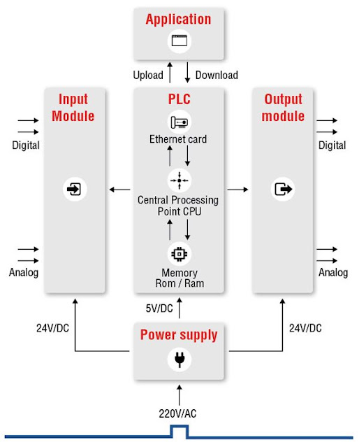
Programmable Logic Controller (PLC) focuses on automating different electro-mechanical processes taking place in various industries. With a well-programmed microprocessor, It has specially designed and implemented controllers which are immune to extremely high and low temperatures, humidity, dust, etc.

Just like any usual program, the coding is programmed on a computer. From here it is transferred to the PLC using a cable. After downloading the programs, these are loaded and stored in the PLC. In order to make sure the programs do not vanish at the time of power cut or switch off, it uses non-volatile memory storage.

It is programmed using a programming language called Ladder Logic. It is already known that it is an industrial computer. In order to program it, a programming language had to be designed in such a way, that the electricians and electrical engineer in an industry could easily understand and feel comfortable enough to code in it.

A Programmable Logic Controller consists of various input and output terminals. Using the input terminals, it interprets the logical states from switches and sensors. There are two logical states also known as high(or 1) and low(or 0). The output from the output terminals is used as a signal for various devices, providing them on/off controls. The electrical engineers understand the ladder logic diagrams and so it was the inspiration behind the programming language used to program its.

The most commons areas of use are in a washing machine, elevators and also traffic signals.

Definition:-

Programmable Logic Controller, more popularly known as PLC is a digital computer without a mouse or a keyboard or a monitor.

                                                            Or

A Programmable Logic Controller, or PLC, is a ruggedized computer used for industrial automation. These controllers can automate a specific process, machine function, or even an entire production line


Understanding PLC:-

Programmable Logic Controller is a small computer which automatically controls various processes and components in an industrial system. For the sake of comparison, let’s take a process that is manual as an example thinks of PLC as a brain controlling a finger on a trigger of an applicator. The brain sends a signal to the finger directing it to pull the finger when something is dispensed and when the brain wants to stop it sends another signal. Like most of the brains, it can multitask and it’s lightning fast Just like that, it can control much input and output signal like direct a paint line to change colors so all the widgets being painted go from one color to other.

Working:-

It communicates to the CPU status of the field devices as well as acts as a tool to control. The programming device is actually a computer loaded with programming software which will allow a user to create and make changes in the PLC software. The memory provides storage media for the PLC program as well as for other data.

How does a PLC work?

The PLC receives information from connected sensors or input devices, processes the data, and triggers outputs based on pre-programmed parameters.
Depending on the inputs and outputs, a PLC can monitor and record run-time data such as machine productivity or operating temperature, automatically start and stop processes, generate alarms if a machine malfunctions, and more. Programmable Logic Controllers are a flexible and robust control solution, adaptable to almost any application.

 There are a few key features that set PLCs apart from industrial PCs, microcontrollers, and other industrial control solutions:

• I/O – The PLC’s CPU stores and processes program data, but input and output modules connect the PLC to the rest of the machine; these I/O modules are what provide information to the CPU and trigger specific results. I/O can be either analog or digital; input devices might include sensors, switches, and meters, while outputs might include relays, lights, valves, and drives. Users can mix and match a PLC’s I/O in order to get the right configuration for their application.


• Communications – In addition to input and output devices, a PLC might also need to connect with other kinds of systems; for example, users might want to export application data recorded by the PLC to a supervisory control and data acquisition (SCADA) system, which monitors multiple connected devices. PLCs offer a range of ports and communication protocols to ensure that the PLC can communicate with these other systems.


HMI – In order to interact with the PLC in real time, users need an HMI, or Human Machine Interface. These operator interfaces can be simple displays, with a text-readout and keypad, or large touchscreen panels more similar to consumer electronics, but either way, they enable users to review and input information to the PLC in real time.

Advantages:-

  • Easily programmable
  • Well shielded to outlast harsh situations
  • Input and output interface available where thousands of input and output can be controlled through a single PLC
  • Highly reliable
  • Easy to maintain

Required skills:-

PLC professionals are experts in concepts, electrical designs. They are also knowledgeable about fabrication and circuit board layout.

Also, they entail meeting with global standards in providing solutions to companies. This ensures making tasks easier by correct relaying of messages and the required team coordination.

Why should we use PLC?

The most common use of it is in washing machines, controlling traffic signals, elevators, etc. Also, we cannot neglect the use of PLCs in industries to monitor and control building systems and production processes.

Why do we need PLC and What can you do with PLC?

It is needed to automate machines in the industry so that human efforts can be reduced thus minimizing the human errors that might occur in the process. Consider a situation where a human handling a system missed to switched the motor on. Imagine the delay it might cause in the operation to begin. The simple solution to solve this is by automating the motor using PLC. So the basic and most important use of it is in the automation of machines.

Who is the right Audience for learning PLC Technologies?

The one-step solution to learning is various available courses online. It is also the best economical and easy way, however, the challenge in learning PLC online is you might learn the names and functioning of software and hardware parts of PLC, the ladder logic diagrams creation or configuring the various modules but just the theoretical knowledge is not enough. In order to be successful, one needs to have a hands-on experience. The one with an interest and background in logic diagrams and controls can start with the PLC programming tool. An elaborate program for an application is not at all an easy task to create. You need a lot of practice and hands-on to do so. In order to excel in this, one can begin from a small machine building company to gain insight and full-fledged skills and experience of the job.

Scope and How this Technology will help you in Career Growth?

As we all know that every industry is moving on to automating its processes and tools, the demand for the programmer is rapidly increasing. Industrial sectors in India like food and beverages, manufacturing industry, oil and gas industry, transport, process industries, etc are also stepping into Industrial Automation. As a matter of fact, technologies like AI, IOT are merging with OT or operational technologies which includes PLC, SCADA, DCS. Renowned companies like SIEMENS, Mitsubishi, Fanuc, Honeywell, etc provide their product and services all over the world. One can find many opportunities in IT and OT sectors as developer, testers, an analyst for it and so we can say that there awaits a bright successful future in automation for the same.

Conclusion

 These applications are specifically highly customized systems. It is cheaper when compared to the price of a specific custom-built controller. Generally, it requires less maintenance and is more robust, henceforth making the things they control work better, despite the environment.


V Curve of a Synchronous Motor:-

V Curve of a Synchronous Motor:- 


                                V curve is a plot of the stator current versus field current for different constant loads. The Graph plotted between the armature current Ia and field current If at no load the curve is obtained known as V Curve. Since the shape of these curves is similar to the letter “V”, thus they are called V curve of synchronous motor.

The power factor of the synchronous motor can be controlled by varying the field current If. As we know that the armature current Ia changes with the change in the field current If. Let us assume that the motor is running at NO load. If the field current is increased from this small value, the armature current Ia decreases until the armature current becomes minimum. At this minimum point, the motor is operating at unity power factor. The motor operates at lagging power factor until it reaches up to this point of operation.

If now, the field current is increased further, the armature current increases and the motor start operating as a leading power factor. The graph drawn between armature current and field current is known as V curve. If this procedure is repeated for various increased loads, a family of curves is obtained.

The V curves of a synchronous motor are shown below.


The point at which the unity power factor occurs is at the point where the armature current is minimum. The curve connecting the lowest points of all the V curves for various power levels is called the Unity Power Factor Compounding Curve. The compounding curves for 0.8 power factor lagging and 0.8 power factor leading are shown in the figure above by a red dotted line.

The loci of constant power factor points on the V curves are called Compounding Curves. It shows the manner in which the field current should be varied in order to maintain constant power factor under changing load. Points on the right and left of the unity power factor corresponds to the over excitation and leading current and under excitation and lagging current respectively.

The V curves are useful in adjusting the field current. Increasing the field current If beyond the level for minimum armature current results in leading power factor. Similarly decreasing the field current below the minimum armature current result results in lagging power factor. It is seen that the field current for unity power factor at full load is more than the field current for unity power factor at no load.

The figure below shows the graph between power factor and field current at the different loads.


It is clear from the above figure that, if the synchronous motor at full load is operating at unity power factor, then removal of the shaft load causes the motor to operate at a leading power factor.

Synchronous Motors: Applications, Starting Methods & Working Principle:-

Synchronous Motors: Applications, Starting Methods & Working Principle:-


                Electrical motors are an Electro-mechanical device that converts electrical energy to mechanical energy. Based on the type of input we have classified it into single phase and 3 phase motors.

The most common type of 3 phase motors are synchronous motors and induction motors. When three-phase electric conductors are placed in certain geometrical positions (i.e. in a certain angle from one another) – an electrical field is generated. The rotating magnetic field rotates at a certain speed known as the synchronous speed.

If an electromagnet is present in this rotating magnetic field, the electromagnet is magnetically locked with this rotating magnetic field and rotates with the same speed of rotating field.

This is where the term synchronous motor comes from, as the speed of the rotor of the motor is the same as the rotating magnetic field.

It is a fixed speed motor because it has only one speed, which is synchronous speed. This speed is synchronized with the supply frequency. The synchronous speed is given by:


Where:

  • N= The Synchronous Speed (in RPM – i.e. Rotations Per Minute)
  • f = The Supply Frequency (in Hz)
  • p = The number of Poles

Construction of Synchronous Motor:-

Usually, its construction is almost similar to that of a 3 phase induction motor, except the fact that here we supply DC to the rotor, the reason of which we shall explain later. Now, let us first go through the basic construction of this type of motor. From the above picture, it is clear that how do we design this type of machine. We apply three phase supply to the stator and DC supply to the rotor.

Main Features of Synchronous Motors:-

  1. Synchronous motors are inherently not self starting. They require some external means to bring their speed close to synchronous speed to before they are synchronized.
  2. The speed of operation of is in synchronism with the supply frequency and hence for constant supply frequency they behave as constant speed motor irrespective of load condition
  3. This motor has the unique characteristics of operating under any electrical power factor. This makes it being used in electrical power factor improvement.

Principle of Operation Synchronous Motor:-

Synchronous motors are a doubly excited machine, i.e., two electrical inputs are provided to it. Its stator winding which consists of a We provide three-phase supply to three-phase stator winding, and DC to the rotor winding.

The 3 phase stator winding carrying 3 phase currents produces 3 phase rotating magnetic flux. The rotor carrying DC supply also produces a constant flux. Considering the 50 Hz power frequency, from the above relation we can see that the 3 phase rotating flux rotates about 3000 revolutions in 1 min or 50 revolutions in 1 sec.

                At a particular instant rotor and stator poles might be of the same polarity (N-N or S-S) causing a repulsive force on the rotor and the very next instant it will be N-S causing attractive force. But due to the inertia of the rotor, it is unable to rotate in any direction due to that attractive or repulsive forces, and the rotor remains in standstill condition. Hence a synchronous motor is not self-starting.

Here we use some mechanical means which initially rotates the rotor in the same direction as the magnetic field to speed very close to synchronous speed. On achieving synchronous speed, magnetic locking occurs, and the synchronous motor continues to rotate even after removal of external mechanical means.

But due to the inertia of the rotor, it is unable to rotate in any direction due to that attractive or repulsive forces, and the rotor remains in standstill condition. Hence a synchronous motor is not self-starting.

Here we use some mechanical means which initially rotates the rotor in the same direction as the magnetic field to speed very close to synchronous speed. On achieving synchronous speed, magnetic locking occurs, and the synchronous motor continues to rotate even after removal of external mechanical means.

  1.  Motor starting with an external prime Mover:     Synchronous motors are mechanically coupled with another motor. It could be either 3 phase induction motor or DC shunt motor. Here, we do not apply DC excitation initially. It rotates at speed very close to its synchronous speed, and then we give the DC excitation. After some time when magnetic locking takes place supply to the external motor is cut off.
  2. Damper winding      In this case, the synchronous motor is of salient pole type, additional winding is placed in rotor pole face. Initially, when the rotor is not rotating, the relative speed between damper winding and rotating air gap flux is large and an emf is induced in it which produces the required starting torque. As speed approaches synchronous speed, emf and torque are reduced and finally when magnetic locking takes place; torque also reduces to zero. Hence in this case synchronous motor first runs as three phase induction motor using additional winding and finally it is synchronized with the frequency.

Application of Synchronous Motors:-

  1. Synchronous motor having no load connected to its shaft is used for power factor improvement. Owing to its characteristics to behave at any electrical power factor, it is used in power system in situations where static capacitors are expensive.
  2. Synchronous motor finds application where operating speed is less (around 500 rpm) and high power is required. For power requirement from 35 kW to 2500 KW, the size, weight and cost of the corresponding three phase induction motor is very high. Hence these motors are preferably used. Ex- Reciprocating pump, compressor, rolling mills etc.

Effect of Temperature On Resistance | Resistance Temperature Coefficient

Effect of Temperature On Resistance | Resistance Temperature Coefficient Fundamental of Electrical Engineering | Effect of Temperature On Re...